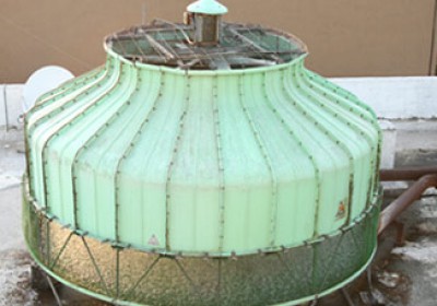
System Design
Mihir Cooling Towers are constructed of the Industry’s most durable materials and are designed for superior performance providing long, trouble-free operation. Nevertheless, proper equipment selection, installation and maintenance are the basis in guaranteeing optimum performance. Several of the key considerations when designing, installing and operating a cooling tower are presented below.
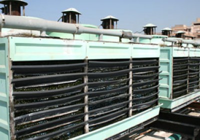
Air Circulation
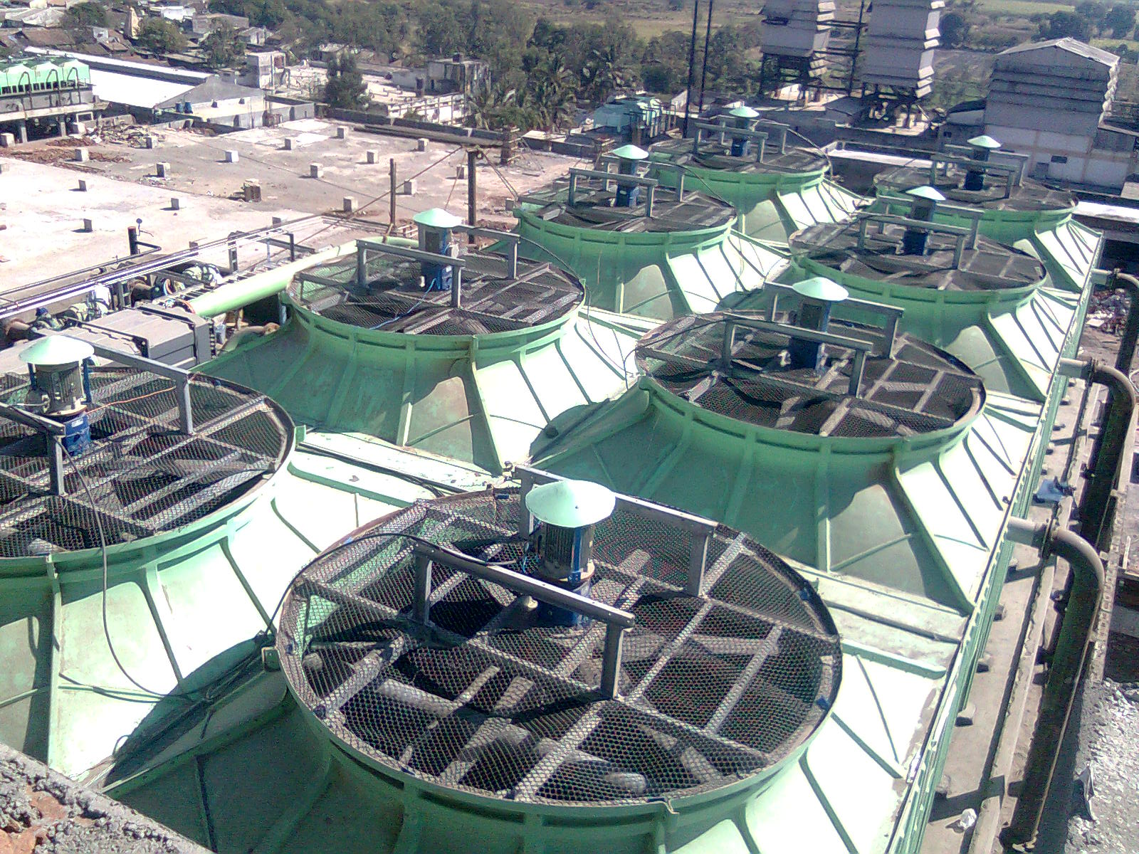
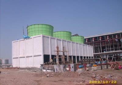
The location of a cooling tower is extremely critical when reviewing system design. Since cooling towers consume large quantities of air, proper spacing is required for the tower to perform properly. The best place to install any cooling tower is on a roof or at ground level away from walls and obstructions. Cooling towers that are located near walls, wells, and enclosures or are flanking high walls must be properly located in order to prohibit the effects of recirculation. Recirculation occurs when some of the hot, moisture-laden air leaving the cooling tower is introduced back into the fresh air inlets. Recirculation results in the inlet wet bulb temperature to be increased causing the capacity of the cooling tower to be significantly reduced. In short, the designer must take care to provide generous air inlet paths.
Maintaining System Cleanliness
A cooling tower removes heat by evaporating a portion of the recirculated spray water. As a general rule, a cooling tower evaporates 3 US GPM per 100 Tons of cooling capacity. As this water evaporates, it leaves behind all of its mineral content and impurities. For that reason, it is essential to blowdown (bleed) an amount equal to that which is evaporated to prevent buildup of impurities. It is very important to provide make up water to replace the water that is both evaporated and bled from the tower system. Make up water should be equal to both evaporation and bleed. (Make up water = Evaporation rate in GPM + Bleed rate in GPM). If adequate blowdown is not maintained, the mineral content in the water will increase until solids eventually deposit and coat the heat transfer surfaces of the unit, causing heavy scaling. Therefore, the blowdown line should be installed in the external piping of the unit. It must be properly sized for the application and be provided with a metering valve and flow measurement device to allow for field adjustment of blowdown rate.
Water Treatment
To control the buildup of dissolved solids resulting from water evaporation, as well as airborne impurities and biological contaminants including Legionella, an effective and consistent water program is required. Simple blow down may be sufficient to control scale, but biological contamination can only be controlled with biocides. Any chemical water treatment used must be compatible with the tower’s materials of construction. Ideally, the pH of the circulating water should fall between 6.5 and 9.0. Batch feeding of chemicals directly into the cooling tower is not a good practice since localized damage to the tower is possible.
Capacity Control
Since the design wet bulb temperature for which a cooling tower is sized occurs only a small percentage of the time, and cooling tower loads tend to be dynamic, some form of capacity control should be employed. Cycling the fan on and off performs the most common form of capacity control. However, this manner of control may result in large temperature differentials and does not provide close control of the leaving water temperature.
Improved methods of capacity control can be better realized through the employment of VFD drives. VFD Drives are an excellent method of maximizing dynamicload- control while reducing operating costs. Simply put, VFD Drives provide a complete range of capacity control.
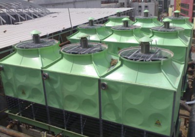
Multiple cell units will provide additional steps of capacity control resulting in substantial reduction in energy costs.
Piping
Cooling tower piping should be designed and installed by professionals who adhere to standard engineering practices. All piping must be supported by properly engineered hangers and supports with allowances made for possible expansion and contraction of the piping system. NO external loads should be positioned on the cooling tower connections. DO NOT anchor any of the piping supports to the cooling tower or its framework. Horizontal pipes located above the tower operating level should be short as possible, as it can cause possible overflow during tower shut down and/or air pockets upon startup.
Managing Biological Contamination
Water quality MUST be checked regularly for biological contamination. If biological contamination is present, a more aggressive water treatment and mechanical cleaning program must be carried out. The water treatment program should be executed by a qualified water treatment organization. It is important to keep all internal surfaces of the cooling tower clean.
CAUTION!
The cooling tower must be located at such distance and direction to prevent the possibility of contaminated tower discharge air being drawn into building fresh air intake ducts. The purchaser of the cooling tower should employ the services of a Licensed Professional Engineer or Registered Architect to certify that the location of the tower is in compliance with the applicable air pollution, fire and clean air codes.